Step 1 - Tools & Equipment
|

|
If there is one thing that I would like to impress upon you, it is the benefit of using quality tools to do your work, The end result of any job is plainly due to the use of good quality tools. And there is also a saving by using good tools, because they last longer, and therefore you do not need to replace them as often.
- Stainless Steel Scissors
- Tweezers or other small no maring clamping device
- (Metric) Number Drills & Pin Vice
- Small Files
- Soldering Iron
- Hold & Fold Tool
- Solder & Flux or Solder Paint
- Snap-off Cutting Blade
- Fine Wet & Dry Paper
- 0.3mm brass wire (0.012")
- Burnishing Brush (Be very Careful)
- Selleys Acrylic Quickgrip
- Cutting Board
Lets get ready to Moddddddeeeeeelllllll
|
Step 2 - Preparing the Model
|


|
- Re-Read the instructions (Yeah I Know!!!!!!)
- The original model needs to be prepared to accept the etched brass components.
- If the kit is already together, parts need to be removed.
- Unscrew the base from the model, and place in a secure place.
- Be careful when handling the body as the detail at the bottom of the model can be damaged. Secure any detail parts in a safe place for later use.
- Remove the hopper filler tops (3 off) and place in a safe place for future use.
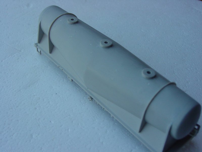
- Remove the ladders and walkway; they can be discarded, but not just yet. There are 2 sets of plastic pins holding the ladders in place. The bottom pins need to be removed as the etch ladder uses these holes, the upper holes need to have the pins kept in place, by cutting the ladder away from the body & leaving the pins to fill the holes. (Refer to top photo at left)
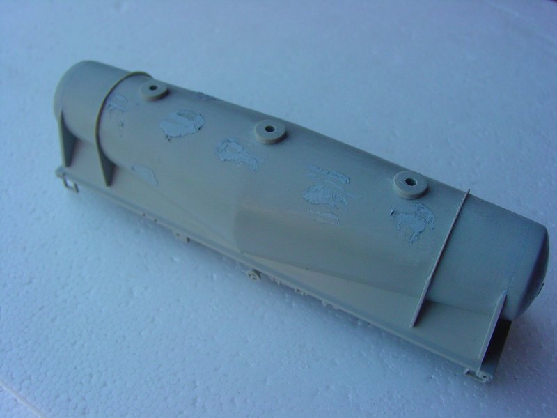
- Glue the remains of any pins left in the body with MEK (dangerous material, please only use in a well ventilated area) from inside and outside the body. Remove any walkway mouldings from the original body, and fill any holes not already filled with plastic pins. Remember to leave the bottom ladder holes as they are used to locate the new ladder. (Refer to 2nd photo at left)
- Use Tamiya (or equivalent) body filler to fill any irregularities in the body when the mouldings were removed. You can also smooth and fill the gaps and creases where the body end caps fit to the main part of the body. (Refer to bottom photo at left)
- A little bit of commonsense can be used at this point: The vehicle is a cement hopper and as such, has remnants of dried cement attached to it from spillage, so the clean up of the body filler need not be as immaculate as the paint job on a band new locomotive. The walkway can also cover some of the removed mouldings, so the level of clean up can be consistent to the level of finish that YOU desire.
|
Step 3 - The Drilling Jig
|

|
- The drilling jig (KRM HO 102) needs to be used to locate the holes for the walkway legs, it simply fits onto the body of the hopper and the holes are located and drilled in the body of the wagon. The instructions for the jig can be found on the card included with the jig. An expanded set of instructions is also available at The Drilling Jig Information Page
|
Step 4 - Working with the walkway etch
|


|
- Be very careful when working with this brass fret as it has some very fine detail, which can be easily damaged. Before starting with the etch, there needs to be some preparation.
- Check that the etch is not damaged or bent
- Clean out the holes in the ladder stiles, with a 0.4mm drill (0.015").
- Clean out the holes in the brake spider wheels and the brake release ratchet and shunters steps with a 0.4mm drill (0.015").
- Cut the walkway away from the fret at the locations indicated.(Refer to Top photo at left)
- Cut away the ladder stiles from the fret and secure for later use.
- The bending sequence for the walkway is important (Refer to 2nd photo at left). The "Hold & Fold" tool is best used here. Be extremely careful that you don't damage the legs of the walkway in the process of bending the small edge pieces.
- To assist in bending the small edge pieces, run a sharp snap off blade lightly on the fold line 2 or three times. But do not use excessive pressure, as this will damage the etch.
- Once you have bent the edge pieces, you can solder or glue (your option) the corners of the landing together, forming a more rigid section. (Refer to 3rd photo at left)
- Bend the legs to 90 degs to the walkway and very carefully test fit the walkway to the body, to check that the holes and the legs line up.
- This procedure is very tricky and the best way to fit the walkway is to locate the short end legs and slowly and carefully work along the walkway locating the legs in holding and preventing the short end from coming out of the holes.
- if you have problems locating the legs, drill out the holes using a 0.6mm drill. This will allow a little more latitude and assist in locating the legs into the holes.
- When the legs are all located into the holes, you will need to level out the walkway.
- Using a small dab of supaglue, glue one of the short legs (From inside the body) at either end of the walkway to hold it in place and carefully level out the walkway. When you are happy that the walkway is level, supaglue all of the legs in place (from the inside of the body). Using the glue sparingly.
|
Step 5 - The Ladders
|


|
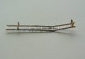
- The ladders are made by folding the stiles and using the folding tabs to gauge their width. (Refer to top photo at left)
- Using the "Hold & Fold" tool, fold the ladder stiles.
- Place both ladder folds together and using longer lengths of 0.4mm wire, fit all of the rungs through the stile holes. (Refer to 2nd photo at left)
- The ladders can also be constructed using the KRM MISC 004 Ladder support forming jig, for more information go to KRM HO 004 -- Ladder Forming Support Jig
- Solder the rungs into place maintaining an even spacing between stiles.
- Cut off excess wire from the sides of the ladders (Refer to 3rd photo at left)and clean up any excess solder, wash the ladders in warm soapy water, clean and dry.(Refer to 4th photo at left)
- Test fit the ladders to the body with the lower pins located in the existing holes
- The top pins on the ladders can be trimmed to fit, and the ladders can also be subtly bent at the kink in the stiles to assist in locating them against the walkway. The ladder opposite the landing side, can have the pins removed completely, (Refer to 5th photo at left) and the landing ladder (Refer to bottom photo at left) will need the pins trimmed down.
- The ladders can now be fitted and soldered to the walkway. The holes for the lower pins can be filled and sanded clean.
- The holes that were drilled for the walkway legs can also be filled and sanded clean, remembering that as previously stated, these are cement wagons and as such, will have cement spillage all over them. Do keep this in mind.
|
Step 6 - Handbrake Gear
|


|
- The handbrake gear uses the existing plastic support bracket to hold the components. Remove the existing plastic brake wheels, but leave the pin in the hole and glue it in place, as it needs to be drilled to allow the brass wire to run through.(Refer to top photo & 2nd photo at left)
- Remove the spider wheels, and the levers & ratchet from the fret, and clean away any trtace of the tabs (there are a spare set of levers/ratchet and a spare brake spider for PING value) (Refer to 2nd photo at left). Hold the jig in position and drill the holes as shown. Continue to do all 4 corner positions.
- Remove the shunters steps from the fret, and clean up the tabs. Fold the steps at the fold lines. The angled gussett goes to the inside of the body (Refer to 3rd photo at left)( there are 2 right hand and 2 left hand steps.
- Check the steps for fit, and trim the pins if necessary. locate the steps into the holes and glue in place using CCA glue. (Refer to bottom photo at left)
|
Step 7 - Shunters Steps
|


|
- The shunters stpes are fitted to holes drilled into the base of the body usimg a drilling jig (F). There are 2 jigs (L & R) Each Jig has 4 holes, this will allow double use of the jig. The holes that are used can be seen in the photo oppposite (Refer to top photo at left)
- Fold the jig at the fold lines and place onto the corner of the body(Refer to 2nd photo at left). Hold the jig in position and drill the holes as shown. Continue to do all 4 corner positions.
- Remove the shunters steps from the fret, and clean up the tabs. Fold the steps at the fold lines. The angled gussett goes to the inside of the body (Refer to 3rd photo at left)( there are 2 right hand and 2 left hand steps).
- Check the steps for fit, and trim the pins if necessary. locate the steps into the holes and glue in place using CCA glue. (Refer to bottom photo at left)
|
Step 8 - Finishing the Job - Hints & Tips.
|
.
|
- For painting the finished vehicle, I would prefer that you use the photos of the prototype in making this decision, as it is purely an individual action, based on what you see in real life. I prefer to weather these vehicle, as they were only ever in a new condition ONCE in their life, from that time on, they became grubby, dirty, rusty & damaged.
- There is much more that can be fitted to these vehicles to make them more complete, things such as handrails, brake clevis parts, and brake rods, wire parts to simulate brake piping, and so much more. The level of detail is only limited by the modellers IMAGINATION, and lets face it, THAT has NO LIMITS
- IMPORTANT INFORMATION
Included in the kit are shunters steps, brake spider wheels, release levers and ratchets. These parts can be fitted to the model; however there is a revision being done on the model at present and anyone with the original kit will be receiving the updated shunters steps & brake parts separately, in the mail at no cost to themselves. This update is being done in the interests of continual improvement. All future kits will have the updated etch in the kit with updated instructions.
- If you have any commnets, feed back, or if you have purchased a kit and do not receive the updated etched components, please don't hesitate to contact me
by email or phone on 61 2 46772462
|